Application of Stevens Modular Fixturingin an Engine Manufacturing Operation By Robert L. Coope, President |
| The constant pressures from customers to improve fuel efficiency, reduce tailpipe emissions, reduce noise, and reduce production costs results in a series of engineering challenges to the manufacturer. The frequent design changes, relatively short product life cycle and the need to maintain a competitive position in the market are all factors that dictate a new approach to manufacturing. The computer controlled machining cell in combination with a versatile workholding system can respond efficiently to a number of manufacturing challenges. |
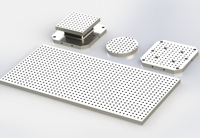
| One manufacturer set up a machining cell consisting of three identical horizontal machining centers in combination with three loading stations, robot machine pallet transfer carts and a master computer which controls and schedules the entire system. Each machine is carefully standardized to accept identical pallets from a random sequence storage area. To provide a convenient, accurate and versatile means of holding workpieces on the pallets, The Stevens Modular Fixturing System was chosen. |
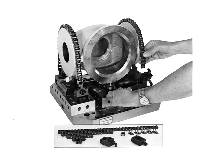
 Figure 1 |
 Figure 2 |
| Figures 1 and 2 show a modular approach to holding and locating a cover casting for machining in two setups on a Stevens subplate. The raw casting is positioned on the upper half of the subplate, using modular edge locators and rest pads for location and manual clamps for holding. Hydraulic work supports are used here to resist cutting forces in unsupported areas. A manually operated screw pump is used in combination with a pressure gage to activate the work supports. |
| The second setup on the lower half of the subplate utilizes features machined in the first operation for location, and manual clamping to hold the part. The subplates are mounted on a Stevens two-sided angle plate, using pull dowels and cap screws for location and attachment. |
| The engineer in charge of the project stated that the flexibility offered by the modular approach for building fixtures was well suited for prototyping, pre-production of parts prior to final configuration of the part design, salvage operations, and for production of obsolete replacement parts for which permanent tooling no longer exists. |
 Figure 3 |
 Figure 4 |
| Figures 3 and 4 illustrate the use of tooling plates made into dedicated holding fixtures in contrast with the pure modular approach shown earlier. The design of the part being machined here has evolved beyond the prototyping stage, thereby justifying an investment in dedicated fixtures. The casting shown is machined in three operations on tooling plates which are located and attached to a Stevens two-sided angle plate. These tooling plates may be easily removed and replaced with other tooling plates or patterned subplates as needed. This approach offers the advantage of easy loading and unloading of parts while retaining the modular advantage of easy removal and replacement of the fixture on the primary component, in this case the two-sided angle plate. |
| In the first operation, (Figure 3), the casting is set up on fixed locators contacting cast target features on the part. Manual clamping is used to secure the part. The second operation fixture (Figure 4), is located on the opposite side of the angle plate. The part locates on round and diamond pins which fit holes machined in the first operation. Again, manual clamps are used to hold the part. For peripheral work done in the third operation, the part is located on a third tooling plate, (figure 3), screwed and doweled to the top of the angle plate. The part is located and clamped in the same way as in the second operation. A finished part comes off each time the pallet is unloaded. |
 Figure 5 |
| Figure 5 illustrates another application of Stevens tooling plates. First and second operation fixtures for machining a cover plate are built into the same tooling plate with an identical fixture mounted on the opposite side of the angle plate. Two parts are fully machined when the pallet is unloaded. The first operation fixture uses manual clamps in combination with hydraulic work supports which are actuated by a hand operated screw pump. The second operation fixture locates the part on features machined in the first operation. |
 Figure 6 |
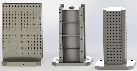
| Figure 6 is a holding fixture representing a relatively advanced stage in the evolution of work holding techniques from prototyping to large scale production. The aluminum casting is located and held on a Silo tooling plate which has been gun drilled and ported for hydraulic clamping. The silo tooling plate has been screwed and doweled to a Stevens Silo Column. The first operation station is located on the upper half of the tooling plate. Hydraulic swing clamps hold the part against fixed locators and hydraulic work supports which prevent deflection of the casting under heavy machining forces. In the second operation, seen just below, the casting is located on features machined in the first operation. Hydraulic swing clamps hold the part for final machining. Potentially an additional three tooling plates may be added to the remaining faces of the Silo column. This would yield four finished parts each time the pallet is unloaded. |
 Figure 7 |
| Figure 7 shows a tilt-down pallet handler used to facilitate loading and unloading of work pieces. This device orients the axis of the machine pallet horizontally. The company strongly emphasizes the importance of process documentation including detailed setup instructions, step by step machining operations, and final inspection of each part. To accomplish this, a “build book” for every part is written and routinely updated to reflect changes. A description of each setup includes detailed CAD drawings using 3D solids, showing the placement of locators, clamps, the work piece, and cutter paths for each operation. The build book includes a flow sheet which describes each machining operation as well as the cutting tools and the tool holders used. Where appropriate, drawings of each tool showing cutter extensions and other tool setting parameters are included. Also included is an inspection sheet detailing how the part is to be checked. |
| This documentation has proven to be particularly helpful when the company is experiencing a high employee turnover rate. New personnel need to be quickly brought up to speed in order to maintain continuity in the production cycle. The inclusion of considerable detail in the build book can be particularly helpful in working with new employees whose skill level is not well known. |